- 您现在的位置:买卖IC网 > Sheet目录1214 > EVAL-ADM1171EBZ (Analog Devices Inc)BOARD EVALUATION FOR ADM1171
�� �
�
�Data� Sheet�
�gate� voltage� of� the� external� FET.� This� minimizes� the� bus� supply�
�voltage� drop� caused� by� the� fault� and� protects� neighboring� cards.�
�As� the� voltage� across� the� sense� resistor� approaches� the� current�
�limit,� a� timer� activates.� This� timer� resets� again� if� the� sense�
�voltage� returns� below� this� level.� If� the� sense� voltage� is� any�
�ADM1171�
�When� the� initial� cycle� ends,� a� start-up� cycle� activates� and� the�
�GATE� pin� is� pulled� high;� the� TIMER� pin� continues� to� pull� down.�
�V� IN�
�1�
�voltage� below� 44� mV,� the� timer� is� guaranteed� to� be� off.� Should�
�the� current� continue� to� increase,� the� ADM1171� tries� to� regulate�
�the� gate� of� the� FET� to� achieve� a� limit� of� 50� mV� across� the� sense�
�resistor.� However,� if� the� device� is� unable� to� regulate� the� fault�
�V� ON�
�V� TIMER�
�2�
�3�
�4�
�current� and� the� sense� voltage� further� increases,� a� larger� pull-�
�down,� in� the� order� of� milliamperes,� is� enabled� to� compensate�
�for� fast� current� surges.� If� the� sense� voltage� is� any� voltage� greater�
�than� 56� mV,� this� pull-down� is� guaranteed� to� be� on.� When� the�
�timer� expires,� the� GATE� pin� shuts� down.�
�TIMER� FUNCTION�
�V� GATE�
�V� OUT�
�The� TIMER� pin� is� responsible� for� several� key� functions� on� the�
�RESET�
�MODE�
�INITIAL�
�CYCLE�
�NORMAL�
�CYCLE�
��and� the� amount� of� time� an� overcurrent� condition� lasts� before�
�the� FET� shuts� down.� On� the� ADM1171-1� ,� the� timer� pin� also�
�controls� the� time� between� auto� retry� pulses.� There� are� pull-up�
�and� pull-down� currents� internally� available� to� control� the� timer�
�functions.� The� voltage� on� the� TIMER� pin� is� compared� with� two�
�V� IN�
�START-UP�
�CYCLE�
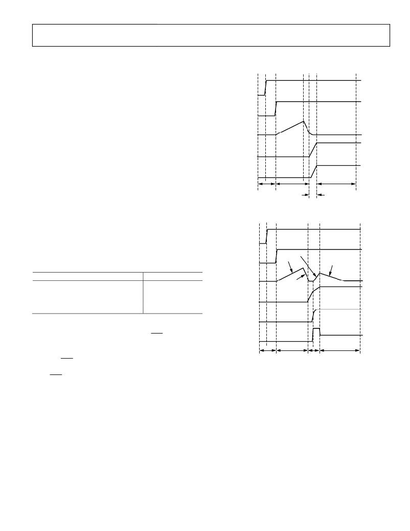
�Figure� 36.� Power-Up� Timing�
�threshold� voltages:� COMP1� (0.2� V)� and� COMP2� (1.3� V).� The�
��V� ON�
�5μA�
�60μA�
�2μA�
�Table� 5.�
�Timing� Current�
�Pull-up�
�Pull-up�
�Pull-down�
�Pull-down�
�Level� (μA)�
�5�
�60�
�2�
�100�
�V� TIMER�
�V� GATE�
�100μA�
�V� OUT�
�POWER-UP� TIMING� CYCLE�
�The� ADM1171� is� in� reset� when� the� ON� (ON-CLR)� pin� is� held�
�low.� The� GATE� pin� is� pulled� low� and� the� TIMER� pin� is� pulled�
�I� RSENSE�
�low� with� a� 100� μA� pull-down.� At� Time� Point� 2� in� Figure� 36,� the�
�RESET�
�INITIAL� START-UP�
�NORMAL�
�ON� (ON-CLR)� pin� is� pulled� high.� For� the� device� to� startup�
�MODE�
�CYCLE�
�CYCLE�
�CYCLE�
�correctly,� the� supply� voltage� must� be� above� UVLO,� the� ON�
�(ON-CLR)� pin� must� be� above� 1.3� V,� and� the� TIMER� pin� voltage�
�must� be� less� than� 0.2� V.� The� initial� timing� cycle� begins� when� these�
�three� conditions� are� met,� and� the� TIMER� pin� is� pulled� high� with�
�5� μA.� At� Time� Point� 3,� the� TIMER� reaches� the� COMP2� threshold.�
�This� is� the� end� of� the� first� section� of� the� initial� cycle.� The� 100� μA�
�current� source� then� pulls� down� the� TIMER� pin� until� it� reaches�
�0.2� V� at� Time� Point� 4.� The� initial� cycle� delay� (Time� Point� 2� to�
�Time� Point� 4)� relates� to� C� TIMER� by� equation�
�Figure� 37.� Power-Up� into� Capacitor�
�CIRCUIT� BREAKER� TIMING� CYCLE�
�When� the� voltage� across� the� sense� resistor� exceeds� the� circuit�
�breaker� trip� voltage,� the� 60� μA� timer� pull-up� current� is� activated.�
�If� the� sense� voltage� falls� below� this� level� before� the� TIMER� pin�
�reaches� 1.3� V,� the� 60� μA� pull-up� is� disabled� and� the� 2� μA� pull-�
�down� is� enabled.� This� is� likely� to� happen� if� the� overcurrent� fault�
�is� only� transient,� such� as� an� inrush� current.� This� is� shown� in�
��t� INITIAL� =� 1.3� ×� C� TIMER� /5� μA�
�(4)�
�and� the� sense� voltage� remains� above� the� circuit� breaker� trip�
�voltage,� the� 60� μA� pull-up� remains� active.� This� allows� the� TIMER�
�pin� to� reach� the� high� trip� point� of� 1.3� V� and� initiate� the� GATE�
�shutdown.� On� the� ADM1171-2� ,� the� TIMER� pin� continues� pulling�
�up� but� switches� to� the� 5� μA� pull-up� when� it� reaches� the� 1.3� V�
�Rev.� A� |� Page� 13� of� 16�
�发布紧急采购,3分钟左右您将得到回复。
相关PDF资料
EVAL-ADM1172EBZ
BOARD EVALUATION FOR ADM1172
EVAL-ADM1175EBZ
BOARD EVALUATION FOR ADM1175
EVAL-ADM1176EBZ
BOARD EVALUATION FOR ADM1176
EVAL-ADM1177EBZ
BOARD EVALUATION FOR ADM1177
EVAL-ADM1178EBZ
BOARD EVALUATION FOR ADM1178
EVAL-ADM1191EBZ
BOARD EVALUATION FOR ADM1191
EVAL-ADM1192EBZ
BOARD EVALUATION FOR ADM1192
EVAL-ADM1275EBZ
BOARD EVALUATION FOR ADM1275
相关代理商/技术参数
EVAL-ADM1172EBZ
功能描述:BOARD EVALUATION FOR ADM1172 RoHS:是 类别:编程器,开发系统 >> 评估演示板和套件 系列:- 标准包装:1 系列:- 主要目的:电信,线路接口单元(LIU) 嵌入式:- 已用 IC / 零件:IDT82V2081 主要属性:T1/J1/E1 LIU 次要属性:- 已供物品:板,电源,线缆,CD 其它名称:82EBV2081
EVAL-ADM1175EBZ
功能描述:BOARD EVALUATION FOR ADM1175 RoHS:是 类别:编程器,开发系统 >> 评估演示板和套件 系列:- 标准包装:1 系列:- 主要目的:电信,线路接口单元(LIU) 嵌入式:- 已用 IC / 零件:IDT82V2081 主要属性:T1/J1/E1 LIU 次要属性:- 已供物品:板,电源,线缆,CD 其它名称:82EBV2081
EVAL-ADM1176EBZ
功能描述:BOARD EVALUATION FOR ADM1176 RoHS:是 类别:编程器,开发系统 >> 评估演示板和套件 系列:- 标准包装:1 系列:- 主要目的:电信,线路接口单元(LIU) 嵌入式:- 已用 IC / 零件:IDT82V2081 主要属性:T1/J1/E1 LIU 次要属性:- 已供物品:板,电源,线缆,CD 其它名称:82EBV2081
EVAL-ADM1177EBZ
功能描述:BOARD EVALUATION FOR ADM1177 RoHS:是 类别:编程器,开发系统 >> 评估演示板和套件 系列:- 标准包装:1 系列:- 主要目的:电信,线路接口单元(LIU) 嵌入式:- 已用 IC / 零件:IDT82V2081 主要属性:T1/J1/E1 LIU 次要属性:- 已供物品:板,电源,线缆,CD 其它名称:82EBV2081
EVAL-ADM1178EBZ
功能描述:BOARD EVALUATION FOR ADM1178 RoHS:是 类别:编程器,开发系统 >> 评估演示板和套件 系列:- 标准包装:1 系列:- 主要目的:电信,线路接口单元(LIU) 嵌入式:- 已用 IC / 零件:IDT82V2081 主要属性:T1/J1/E1 LIU 次要属性:- 已供物品:板,电源,线缆,CD 其它名称:82EBV2081
EVAL-ADM1178MEBZ
功能描述:BOARD EVALUATION FOR ADM1178 RoHS:是 类别:编程器,开发系统 >> 评估演示板和套件 系列:- 标准包装:1 系列:- 主要目的:电信,线路接口单元(LIU) 嵌入式:- 已用 IC / 零件:IDT82V2081 主要属性:T1/J1/E1 LIU 次要属性:- 已供物品:板,电源,线缆,CD 其它名称:82EBV2081
EVAL-ADM1184
制造商:AD 制造商全称:Analog Devices 功能描述:Evaluation Kit for ADM1184 ?±0.8% Accurate Quad Voltage Monitor
EVAL-ADM1184EBZ
功能描述:BOARD EVAL FOR ADM1184 RoHS:是 类别:编程器,开发系统 >> 评估演示板和套件 系列:- 标准包装:1 系列:- 主要目的:电信,线路接口单元(LIU) 嵌入式:- 已用 IC / 零件:IDT82V2081 主要属性:T1/J1/E1 LIU 次要属性:- 已供物品:板,电源,线缆,CD 其它名称:82EBV2081